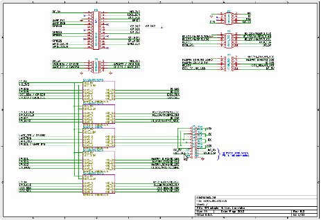
This board translates bidirectionally inputs/outputs of the Raspberry Pi's GPIO from 3.3V to 5V TTL levels.
The second revision of Raspberry Pi (indentifiable because there are two holes for mechanical subjection and an extension of the GPIO of 8 pins without terminals, P5) allows a GPIO extension soldering terminals on P5. The advantages of P5 are: 1) use of a 2nd TWI/I2C bus (if you don't use S5 for Raspberry Pi's camera) and 2) direct access to RTS and CTS signals from UART.
3Bpi's P2 is an UART serial communication port. Through jumpers Raspberry Pi can be set as master or slave. To communicate as master without hardware flow control jumpers should be set on RX_A and TX_A. To communicate as slave jumpers should be set on RX_B and TX_B. If hardware flow control is needed jumpers should be set on CTS_A and RTS_A working as master or on CTS_B and RTS_B as slave. Using CTS and RTS is possible if Raspberry Pi's P5 connector is soldered. If P5 is not soldered (or using first revision of Raspberry Pi) levels at I2C0_SCL and I2C0_SDA can be forced through jumpers.
3Bpi's P3 can be used as input/output port, as I2C0 bus (P5 soldered and not using camera's S5) or as SPI3 (for instance a resistive touchscreen using two SPI chips, one for screen and other for resistive touch control).
3Bpi's P4 can be used as input/output, as TWI/I2C bus (I2C_0 in Raspberry Pi first revision and I2C_1 in second revision) or as SPI bus using SPI4. 3Bpi's video introduction: Code used in this video : p4v2_01.c
This design is based on Jim Hagerman's article, Nokia Mobile Phones, San Diego, California, entitled "Two Transistor Form Bidirectional Level Translator".